
SAP2000 tutorial course for beginners - 3: Modeling and analysis of beams
Introduction:
This is the third SAP2000 tutorial, at the end of this tutorial you'll be able to make a full structural analysis of any beam, and to display shear and moment diagrams. Moreover, the section properties and materials will be taken into consideration because they affect the deflection and the structural elements self weight.


Reading Results:
User of SAP wants at the final stage to have required output. This output could be something like major bending moment on beams or shear forces. In this part user will practice modeling a simple determinant structural system and having analysis in order to get required output.
Example 1:Represent the cantilever system (5m R50x50 section) shown in figure 1 and display axial force, bending moment, and shear force diagrams.
 |
| [Fig.1] |
After creating the system in SAP, user is asked to analyze it. To analyze any structure system in SAP follow these steps: 1- Choose Analyze➥ set analysis option ➥ choose XZ plane since the system we are analyzing is built at the XZ plane (see figure 2) ➥ click ok.
 |
| [Fig.2] |
2- To start analysis: Analyze ➥ Run Analysis (refer to figure 2 to see this option. Indeed user can hit on F5 without going through this process.
3- Before displaying results user can check the deflected shape. Deflected shape always gives an indication to your work. To display deformed shape click: display ➥ show deformed shape (see figure3).
 |
| [Fig.3] - Displaying deformed shape in SAP |
4- The first thing user want to display is the axial force diagram; but since there is no axial load at this beam it is expected to have zero axial force diagram. To display axial force diagram: Display ➥ show forces/stresses ➥ Frame/Cables ➥ choose axial force component ➥ ok. (See figure 4).
Note nothing will display since zero values will generate nothing.
Note nothing will display since zero values will generate nothing.
 |
| [Fig.4] - Displaying axial force diagram |
5- To display Shear force diagram follow a similar procedure: Display ➥ show forces/stresses ➥ Frame/Cables ➥ choose Shear2-2 ➥ ok (see figure 5+6).
 |
| [Fig.5] - Displaying shear force diagram |
 |
| [Fig.6] - Shear force diagram |
Question: Shear force diagram is not as expected. Expectations suggest that shear force diagram is a constant value at each single station of this beam. Why do we have this shape?
6- To display bending moment force diagram follow a similar procedure:
Display ➥ show forces/stresses ➥ Frame/Cables ➥ choose Moment M3-3 ➥ ok (see figure 7).
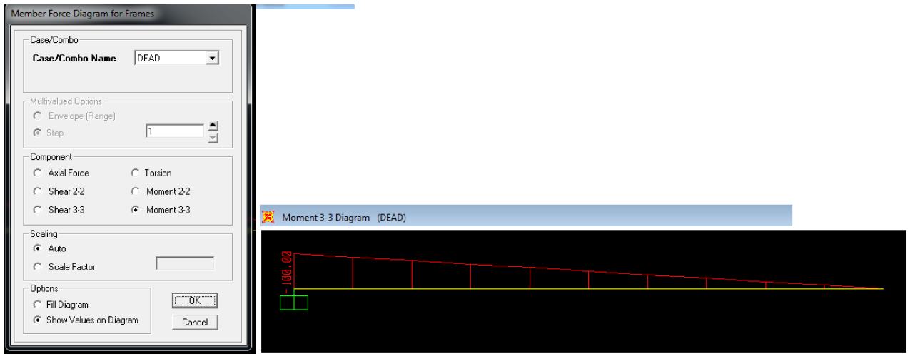 |
| [Fig.7] - Displaying bending moment diagram |
Note: Bending moment diagram appears in unexpected way; according to our way in drawing, moment value in cantilever at fix support has negative value and therefore it is drawn inverted (under the beam). To change the display of moment follow these steps: Options ➥ Uncheck “Moment Diagrams on Tension Side” (see figure 8).
 |
| [Fig.8] |
Question: Moment value at the fix support can be calculated simply; Calculate it and compare your value with that shown by SAP. Explain the reason of differences if exist
Deflection Calculation: SAP can calculate deflection at each point. To view deflection values follow these steps: 1- Display Bending moment diagram.
2- Select the beam and then right click. You should see a window as shown in figure 9. Make all options as shown in figure 9.
Deflection Calculation: SAP can calculate deflection at each point. To view deflection values follow these steps: 1- Display Bending moment diagram.
2- Select the beam and then right click. You should see a window as shown in figure 9. Make all options as shown in figure 9.
 |
| [Fig.9] - Displaying deflection in cm |
Defining moments on a structural system: User can use SAP not only to define various shapes of loads. SAP has the ability to let user define moments at structural systems. Following figure is a solved example (look at figure 10 and figure 11).
 |
| [Fig.10] - Simply supported beam with point load and bending moment |
 |
| [Fig.11] - Solution of the figure |
first and before starting defining moment on SAP user must understand what this moment is trying to do. First remember that you are working at the XZ plane, then try to imagine how this moment is trying to rotate section of beam around Y axis, figure 11 will help you imagine what is happening. Determination of moment orientation.
 |
| [Fig.12] |
Now after understanding figure 11 you can have the first conclusion. The moment is trying to twist section around Y-axis. Second thing to be concluded is the sign of the moment. Apply the right hand rule and you will find that the sign is positive. Now build this simple structural system using SAP:
1- Create the suitable grid system.
2- Assign the point load.
3- Assign moment based on the explanation in the previous figure. Choose the point ➥ Assign ➥ Joint loads ➥ Forces ➥ beside moment about global Y fill the blank with +2 KN.m value (see figure 13).
1- Create the suitable grid system.
2- Assign the point load.
3- Assign moment based on the explanation in the previous figure. Choose the point ➥ Assign ➥ Joint loads ➥ Forces ➥ beside moment about global Y fill the blank with +2 KN.m value (see figure 13).
 |
| [Fig.13] - Assigning moment on beam |
4- Self weight is neglected. Do not forget to make self weight multiplier 0.
5- Analyze the system (hit F5).
6- Display shear force diagram and compare it with that shown in the example (see figure 14).
5- Analyze the system (hit F5).
6- Display shear force diagram and compare it with that shown in the example (see figure 14).
 |
| [Fig.14] - SAP results vs hand solution |


No comments: