
SAP2000 tutorial course for beginners - 6: Solving trusses and arches
Introduction:
This is the last SAP2000 tutorial, at the end of this tutorial you'll be able to make a full structural analysis of any truss and areches and to display shear, moment and member forces diagrams as well.


Solving 2D Trusses using blank template (Continued)
Example 1: draw and analyze the truss shown in figure 1 using SAP2000.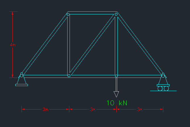 |
| [Fig.1] |
1- build the suitable grid system for the truss system (3 spacing in x- 1 spacing in z).
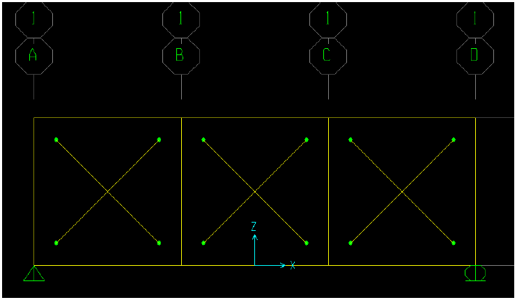
2- Draw the element of trusses using “moment releases” option as pinned instead of continuous. This will create moment releases at both ends (see figure 2).
 |
| [Fig.2] |
3- Assign supports and loads and set self-weight multiplier to be zero to neglect self-weight.
4- Run analysis.
5-Display deformed shape and non-deformed shape at the same time. To do this see figure 3.
5-Display deformed shape and non-deformed shape at the same time. To do this see figure 3.
 |
| [Fig.3] |
6- To display displacements at any point select it and then right click (see figure 4).
 |
| [Fig.4] |
7- Change units to mm to get better displacement (see figure 5).
 |
| [Fig.5] |
Solving 2D Trusses using 2D truss template:
If user selects 2D truss template then awareness must be paid to end releases. Following steps are for choosing default vertical truss:
1- Choose 2D truss template as shown in figure 6.
1- Choose 2D truss template as shown in figure 6.
 |
| [Fig.6] |
2- End releases can be checked in two ways: A) - click on “set display options” then check releases as shown in figure 7.
 |
| [Fig.7] |
Figure 8 indicates the members with moment releases. SAP suggestions can be modified manually by user.
 |
| [Fig.8] |
B) Select any member than right click on it so you can display moment releases in the member selected as shown in figure 9.
 |
| [Fig.9] |
Trusses problems:
Problem #1:
Build this truss using SAP 2000 - see fig.10
Determine all the member forces
Identify the zero forces members
 |
| [Fig.10] |
Problem #2:
Build this truss using SAP 2000 - see fig.11
Determine all the member forces
Identify the zero forces members
 |
| [Fig.11] |
Problem #3:
Determine all the member forces
Identify the zero forces members
See fig.12
 |
| [Fig.12] |
Problem #4:
Determine the force in members FG and DG of the truss shown in the figures below. State whether the members are in tension or compression.
Note: The reactions at the supports have been calculated.
 |
| [Fig.13] |
Creating arches using SAP2000:
Arches can easily be created using SAP if user learn how to build cylindrical systems. So learning how to build cylindrical systems is the first thing to be done.
Building a cylindrical grid is an easy process in SAP. To Define a cylindrical system follow these steps:
1- Open a new file; Choose Blank.
2- Right click ➥ Edit grid data ➥ high light “GLOBAL” ➥ Modify/show system ➥ Quick start.
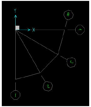
3- To draw cylindrical grid choose cylindrical tab. Cylindrical systems are defined by radius (R) and Theta (ϴ) (see figure 14)
Quick start window to define cylindrical system
Example 4: Draw the grid line shown in figure 15.
1- As mentioned before user needs to define R & ϴ, R is 6 m as shown in figure 10. User can determine ϴ simply by dividing 180 on 6 (6 is number of angles):
2- Input at quick start must be as shown in Fig. 15. Number of grid lines along radius can easily be determined using this relation: Number of grid lines along radius = No. of radiuses+1
Exercise: Draw the cylindrical system shown in figure 17. Use R=6 m.
Example: Build arch shown in figure 18 using SAP.
1- SAP do not draw curves. Curves are represented as a small line segments connected to each others. This can be understood by looking at figure 19.
2- The much lines you have the more accurate you are in the simulation of the arch.
3- This arch will be divided into 8 parts. You must understand that this number is not the only correct way to simulate the arch. You may use less or more lines. Now look at figure 20.
4- Now user is going to create cylindrical system. Note that arch lies on xz plane while proposed grid will be drawn in xy plane.
5- Create a cylindrical system with the same input shown in figure 21.
User must now have a cylindrical system exactly as the one shown in figure 22.
6- Draw the arch in XY plane. User must have the same result as shown in figure 23.
7- This step is about transferring the drawn arch from xy to xz. To do that, first select arch elements ➥ Edit ➥ replicate ➥ radial (see figure 24).
After doing the previous step user will have same as shown in figure 25.
8- Now change view to RZ (actually xz) to view the arch in 2D (see figure 26).
9- Assign the supports to finish building the system (see figure 27).
Building a cylindrical grid is an easy process in SAP. To Define a cylindrical system follow these steps:
1- Open a new file; Choose Blank.
2- Right click ➥ Edit grid data ➥ high light “GLOBAL” ➥ Modify/show system ➥ Quick start.
3- To draw cylindrical grid choose cylindrical tab. Cylindrical systems are defined by radius (R) and Theta (ϴ) (see figure 14)
Quick start window to define cylindrical system
 |
| [Fig.14] |
Example 4: Draw the grid line shown in figure 15.
 |
| [Fig.15] |
1- As mentioned before user needs to define R & ϴ, R is 6 m as shown in figure 10. User can determine ϴ simply by dividing 180 on 6 (6 is number of angles):
2- Input at quick start must be as shown in Fig. 15. Number of grid lines along radius can easily be determined using this relation: Number of grid lines along radius = No. of radiuses+1
 |
| [Fig.16] |
Exercise: Draw the cylindrical system shown in figure 17. Use R=6 m.
 |
| [Fig.17] |
Example: Build arch shown in figure 18 using SAP.
 |
| [Fig.18] |
1- SAP do not draw curves. Curves are represented as a small line segments connected to each others. This can be understood by looking at figure 19.
 |
| [Fig.19] |
2- The much lines you have the more accurate you are in the simulation of the arch.
3- This arch will be divided into 8 parts. You must understand that this number is not the only correct way to simulate the arch. You may use less or more lines. Now look at figure 20.
 |
| [Fig.20] |
4- Now user is going to create cylindrical system. Note that arch lies on xz plane while proposed grid will be drawn in xy plane.
5- Create a cylindrical system with the same input shown in figure 21.
 |
| [Fig.21] |
User must now have a cylindrical system exactly as the one shown in figure 22.
 |
| [Fig.22] |
6- Draw the arch in XY plane. User must have the same result as shown in figure 23.
 |
| [Fig.23] |
7- This step is about transferring the drawn arch from xy to xz. To do that, first select arch elements ➥ Edit ➥ replicate ➥ radial (see figure 24).
 |
| [Fig.24] |
After doing the previous step user will have same as shown in figure 25.
 |
| [Fig.25] |
8- Now change view to RZ (actually xz) to view the arch in 2D (see figure 26).
 |
| [Fig.26] |
9- Assign the supports to finish building the system (see figure 27).
 |
| [Fig.27] |


No comments: