
Etabs tutorial for buiginners - Part 1
Introduction:
Etabs is another software produced by CSI. Etabs is specific for high rise buildings, and the aim
of using it is to build 3 dimensional models.

1- Units Set:
Before you start any model make sure you are using the proper units, figure 1 illustrates how toset units before staring any job in Etabs.
 |
[Fig.1] |
To start a new model do as shown if figure 2.
 |
| [Fig.2] |
Now a window as shown in figure 3 will appear to you, and as it is our first time, let us click on “No” option (the difference between 3 options will be discussed in an advance stage).
 |
| [Fig.3] |
 |
[Fig.4] |
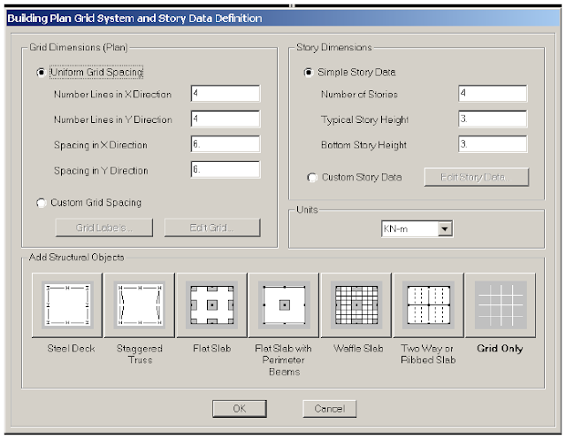
In this stage we will keep everything as set by default, now click ok, you must have the same as shown in figure 5.
 |
| [Fig.5] |
3- Defining a new material:
At this stage user are asked to define a new concrete material, the name of the defined material will be B300 (as known at the Palestinian market).
Discussion question: What is meant by B300?
Now do as shown in figure 6.
 |
[Fig.6] |
According to ACI code Modulus of Elasticity can be calculated due to this relation
To define a beam section (50x50 cm) do as shown in figure 7.
 |
| [Fig.7] |
 |
[Fig.8] |
User has the option to delete sections suggested by the software, to do so select all the sections excluding B50x50 and click delete (see figure 9).
 |
| [Fig.9] |
User is asked to define a solid slab with 20 cm thickness, to do so, do as shown in figure 10.
 |
| [Fig.10] |
Now delete the default area properties exactly as done in the frame sections (see figure 11).
 |
| [Fig.11] |
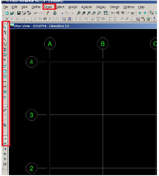
Etabs by default suggests 2 windows, one is 2D view (plan view) and the other is 3D; this to let user see changes done on plan as reflected on the 3D model. Usually user has to draw in the plan view as it is simpler to control.
User can choose the drawing tool either from the buttons above or through short cuts to the left of the screen (see figure 12).
 |
[Fig.12] |
To use the tool of drawing a line (beam is considered as a line object) do as shown in figure 13.
 |
[Fig.13] |
 |
[Fig.14] |
Now use the option “Undo”  to ignore the last step (actually we are going to draw lines using the short cuts to the left of the screen). To do so click on the tool shown in figure 15.
| [Fig.15] |


So nice I am enjoying for that post as for u latest version of this Security tool Available
ReplyDeleteweather-pro-crack
extreme-picture-finder-crack
systools-hard-drive-data-recovery-crack
etabs-crack
Boosting Your Online Success, One Click at a Time.
ReplyDeleteSysTools Hard Drive Data Recovery Crack