
Etabs tutorial for buiginners - Part 3

Defining Load Cases:
User can easily add the number required of load cases, to do so see figure 1.
 |
| [Fig.1] |
Already program defines two load cases (dead and live), if user wishes to add a new load case (wind load for example) then first the name will be changed to be wind and load type will be set as wind instead of dead (see figure2), self-weight multiplier will be changed to zero automatically; as this option can be defined with DEAD type only. Now click at “Add New Load”.
 |
| [Fig.2] |
Now user must have as shown in figure 3.
 |
| [Fig.3] |
Defining Load Combinations
User can define load combinations manually (mentioned at SAP manual) or can use default load combinations (according to ACI code). At this step user will learn how to let Etabs define load combinations automatically. Now see figure 4 and do as shown to complete defining load combinations.
 |
| [Fig.4] |
Now check load combinations defined by Etabs (see figure 5).
 |
| [Fig.5] |
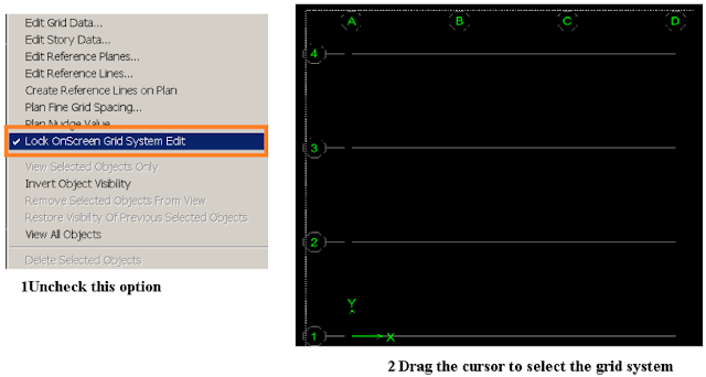
How to delete an existing grid line?
User can easily delete a grid system by doing as shown in figure 6, but first right click at any empty space on the screen.
 |
| [Fig.6] |
Now click Delete button.
Editing Story Data:
User can easily edit stories defined (names, elevation) by doing as shown in figures 7&8 respectively.
 |
| [Fig.7] |
 |
| [Fig.8] |
Exercise 1:
Edit stories data to be exactly as shown in figure 9.
 |
| [Fig.9] |
Similar Story Option Illustration:
When user start drawing at a plan, then the reflection of his work will depend on the option selected to the right of the screen
 , if it is selected to be One Story, then what user is doing will be only reflected on the only story user is working at. If the option is changed to be All Stories, then the reflection will be to all stories, and the same thing is applicable for the last option (Similar Stories).
Exercise 2:
Practice the previous explanation by drawing any section at the planes 3 times: once by choosing One story, then All Stories, and finally Similar stories.Glue Section to a Grid System
What glue a section to grid supposed to mean? User will figure this quality by practicing the following exercise.Exercise 3:
1- Define simple uniform grid spacing: 4x4 system with 7 m uniform spacing in each direction (see figure 10).
 |
| [Fig.10] |
2- Draw any default beam section at one row of the grid (as shown in figure 11).
 |
| [Fig.11] |
3- Right click at any empty space in the screen ➥ Edit grid data ➥ Select the grid system ➥ modify/show system do as shown in figure 12.
 |
| [Fig.12] |
 |
| [Fig.13] |


No comments: