
Full structural analysis and design of commercial building project - Modeling and design (part - 3)
Modeling and Analysis
1. Structural Modeling of Al-Nijmah Commercial CenterA three dimensional structural model of Al-Nijmah Commercial Center building established using ETABS software. The model built using preliminary cross sections taken from the introduction to graduation project for columns and beams. Solid slab of 35 cm thickness on (50cm X75 cm) beams is used for all floors so the beam depth of 75 cm serves as preliminary dimension for stiff beam as required by tabulated coefficients method.
After analysis, sections of beams and columns changed such that they resist applied loads.
 |
| Figure 5. 1: Three Dimensional Structural Model of the Commercial Center |
 |
| Figure 5. 2: Three Dimensional Shear Wall System the Commercial Center |
The structure will be designed to resist both gravity and lateral loads, therefore the slab must be defined as rigid diaphragm such that it supports the gravity load, transfer lateral loads to the vertical structural elements such as shear walls and moment resisting frames according to their relative stiffness.
It's important that the model in the ETABS or any structural analysis software that the model includes the stiffness of the elements which resist the lateral load, and this can be achieved by considering cracked section properties of the structural elements defined in ETABS model by reducing moment of inertia as specified in ACI-10.10.4.1 as follows:
➧ Compression members:
Columns …. 0.7 Ig
Walls-Uncracked ………0.7 Ig
Cracked ……….0.35 Ig
➧ Flexural members:
Beams…….0.35 Ig
Flat Slabs and flat plates…….0.25 Ig
Where: Ig is the gross moment of inertia of the element cross section.
2. Static and Dynamic Analysis of Al- Nijmah Commercial Center
5.2.1 Definition of equivalent static force procedures done according to UBC97 code. So two load patterns defined in both X and Y direction. Different parameters needed for analysis are shown in figure 5.3.
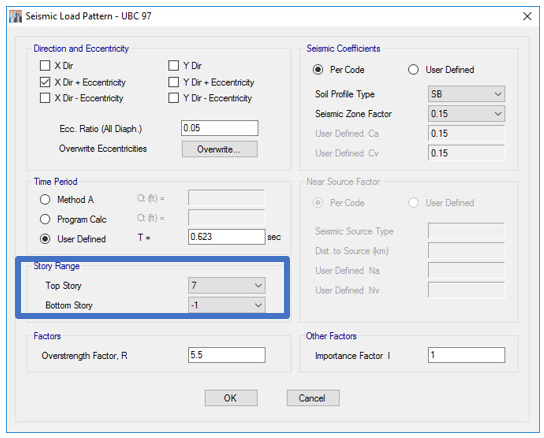 |
| Figure 5. 3: Definition of Equivalent Static Lateral Force in the X-Direction in ETABS |
It is obvious from figure 5.3 that story range defined from basement 1 to top floor so that the free height of the building will be only considered in the calculation of base shear.
2. Dynamic Analysis Definition in ETABS
As mentioned in chapter 4, dynamic lateral force procedure will be used as an analysis method which takes into consideration dynamic properties of structure and earthquake.
Dynamic lateral force procedure can be carried out using either of the two approaches:
➧ Time history analysis
➧ Response spectrum
In this project the dynamic lateral force procedure performed using response spectrum analysis as a dynamic analysis which is permitted by UBC1657.5.3 for soil profiles SA, SB, SC, or SD.
Response Spectrum Analysis:
Definition of response spectrum function in ETABS is shown in figure 5.4.
 |
| Figure 5. 4: Definition of Response Spectrum According to UBC-97 |
As the response spectrum function has been defined, two load cases in the X and Y directions are defined as shown in figures 5.5 and 5.6 respectively.
 |
| Figure 5. 5: Definition of Response Spectrum Load Case in the X-Direction |
 |
| Figure 5. 6: Definition of Response Spectrum Load Case in the Y-Direction |
3. Scaling of Dynamic Analysis Results
For the response spectrum analysis, UBC97 requires in sections 1631.5.4 and 1659.7.3 that if base shear determined by response spectrum is less than that determined by equivalent static lateral load procedure; it should be scaled up to the base shear determine by equivalent static lateral load procedure. Therefore, the initial scale factor for response spectrum is (I×g)/R, where g is the acceleration due to gravity (9.81 m/sec2), R =5.5 for building frame system and R=6.5 for dual system and I =1. After the analysis, base shear determined by response spectrum in both directions must be scaled to base shear from equivalent static method.Therefore, after the analysis static base shear founded to be greater than the dynamic one and the scale factor modified so the response spectrum base shear is scaled up to the static shear.
| Direction | Static Analysis base shear (KN) | Response Spectrum base shear (KN) | |
|---|---|---|---|
| Before scaling | x | 4883 | 3228 |
| y | 4830 | 3210 | |
| After scaling | x | 4833 | 4833 |
| y | 4830 | 4830 |
4. Load Combination
Load Combinations generated by ETABS in accordance with ACI-318 and UBC97 and checked manually depending on ACI-9.2.1 and UBC 2211.4 Part I, section3. Load combinations are:
Combination 1= 1.4 D.L
Combination 2= 1.2 D. L + 1.6 L. L
Combination 3= 1.3 D. L + 1 L. L+ (1 RSx + 0.3 RSy)
Combination 4= 1.3 D. L + 1 L. L+ (0.3 RSx + 1 RSy)
Combination 5= 0.8 D. L + (1 RSx + 0.3 RSy)
Combination 6= 0.8 D. L + (0.3 RSx + 1 RSy)
Orthogonal effects that can be noted in load combinations are to be considered in designing structural elements for 100 percent of the design seismic forces in one direction plus 30 percent in the perpendicular direction as stated in UBC 1633.1.
Design and Detailed Drawings
1. Analysis and Design of Slabs
Analysis and Design of the Floors Slabs
Each slab within the structure was exported to be analyzed and designed using SAFE software. Slab divided into strips in both directions, each strip has a width of one meter. Then analysis and design done for these strips. |
|
Figure 6. 1: Middle and Column Strips Distribution Along X-Direction |
 |
|
Figure 6. 2: Middle and Column Strips Distribution Along Y-Direction |
Analysis and Design of Ramps
The ramps within the basements floors designed as simply supported one-way solid slabs of 28 cm thickness. They will support a live load of 8 KN/m².
Analysis and Design of Staircase Slab
Staircase slab designed as one way simply supported solid slab of 22 cm thickness to carry a live load of 5 KN/m2 and its own weight.2. Design of the Structural Frames
Design of Columns
As the analysis results of the three dimensional model had been accepted as shown in chapter 3, a column has been chosen to be designed manually and the result compared to that given by the ETABS to give approximately the same results. So, design of all columns within the structure taken from the software.
The following table summarize columns cross section for the fifth basement floor as can be also seen from the detailed structural drawing for columns.
Table 6. 1: Columns Cross Section in the Fifth Basement Floor
| Column Label | Column Cross Section | Basement floors Reinforcement | Reinforcement Ratio (%) |
|---|---|---|---|
| C1 | 30X30 | 8 Φ 16 | 1.79 |
| C2 | 60X30 | 12 Φ 16 | 1.34 |
| C3 | 55X55 | 16 Φ 18 | 1.34 |
| C4 | 60X60 | 32 Φ 18 | 2.26 |
| C5 | 65X65 | 24 Φ 20 | 1.78 |
| C6 | 70X70 | 24 Φ 20 | 1.82 |
| C7 | 75X75 | 24 Φ 20 | 1.34 |
| C8 | 80X80 | 24 Φ 20 | 1.18 |
| C9 | 90X90 | 28 Φ 28 | 2.13 |
| C10 | 100X100 | 28 Φ 25 | 1.37 |
| C11 | 120X120 | 32 Φ 25 | 1.09 |
| C12 | 120X120 | 40 Φ 30 | 1.96 |
| C13 | 130X130 | 40 Φ 28 | 1.46 |
| C14 | 130X130 | 44 Φ 32 | 2.09 |
Design of Beams
Design of beams was taken from ETABS after a sample calculation done to verify ETABS analysis results. The preliminary cross section of 50 cm X 75 cm changed for some beams and remains the same for others. The following table summarize beams cross sections for all floors as can be also seen from floors plans drawings and the detailed structural drawing for beams.Table 6. 2:Beams Cross Sections
| Beams Cross Sections |
|---|
| 35X35 (hidden) |
| 40X50 |
| 50X75 |
| 60X80 |
Transfer Beam:
The transfer beams are members that will transfer the axial load of the tension and compression columns, to adjacent columns in order to eliminate some columns in the 6th and 7th floors for architectural purposes.These beams are resting on columns of dimensions ranges from 60cm x 60cm to 100cm x 100cm. Depth of transfer beam is larger ordinary one because of high shear resulted from concentrated axial load of column.
For beams details see drawings of (B8, B9, B12, B13 and B14) In the 6th floor.
3. Shear Walls and Boundary Elements Design
Shear walls designed using ETABS for shear forces, axial and bending effects. Manual check done for design results.Shear wall system within the structure is assumed to carry almost the lateral load from the earthquake forces so they should be designed as special shear walls according to ACI21.9.
A check for the need of boundary elements done and results shown that no need for boundary elements. Boundary elements can be defined as a compression member to be provided along boundaries of walls. Check can be done by two methods which are displacement based and stress based methods. Stress based method used based on ACI21.9.6.3. Manual check and detailing of all shear walls done according to ACI21.9.2 -21.9.6.
4. Analysis and Design of Mat Foundation
Mat foundation analysis results exported from ETABS to SAFE and designed using SAFE.
Depth of mat foundation determined to avoid punching shear, for huge columns drops used to avoid punching shear. Punching shear checked using SAFE and checked manually.
 |
|
Figure
6. 3: Punching shear check for a) column does not need a drop. b)
column needs a drop c) The same column in (b) after drop added |
Value of 0.93 in Figure 6.4 (a) is the ratio between punching shear and concrete capacity. If the value less than 1 then the depth of mat foundation is safe for punching shear.
Check for stresses done so that all stresses are less than bearing capacity of soil and no existence for uplift forces. Mat foundation designed by SAFE, checked and detailed manually.
Φ 25/15 cm is used in both directions at bottom and top of mat foundation and an additional bars used where needed.
5. Analysis and Design of Basement and Retaining Walls
Basement walls modeled and analyzed using SAP2000 program, and designed manually, just the same as one-way solid slab design.
The sample basement wall that is shown in the figure below has a total height of 17.75 m and extending through 7 floors, and it has a total thickness of 45 cm.
 |
Figure 6. 4: Sample basement wall model |
Basement wall modeled as shown in the figure simply supported at the level of each slab, and it is subjected to horizontal earth pressure due to the backfill behind it and to vertical load due to building loads (dead and live). The thickness of the wall is determined based on concrete shear strength, which must be at least equals the ultimate applied shear.
Flexural reinforcement in both directions calculated for 1m strip as done in solid slabs design.
Conclusion
All columns are checked for slenderness and sway, resulting in short and non-sway columns, for which no magnification of moment is to be needed. Reinforcement of columns is about 1-3% of gross area, this is to ensure a ductile behavior of columns.
Shear walls added to the east building to carry lateral loads. Shear walls through earthquakes effects are extensively investigated to determine design criteria and forces. Shear walls design is based on shear failure and checked for flexure.
Basement walls thickness determined based on shear failure. The main reinforcement in basement walls is in the vertical direction and the secondary reinforcement is placed in the horizontal direction.
In the west building, building Frame system used in which shear walls resist lateral loads and frames resist vertical loads while in the east one dual system used in which both shear walls and frames resist lateral loads and vertical loads carried by frames.
Mat foundation is used to support the stresses of the superstructure. The bearing stress of the soil due to loadings was between 120 and 450 kN/m2. The depth of the foundation for most columns is 1200 mm and some critical columns needed a larger depth and hence drops used. Minimum reinforcement controls the design of mat foundation.
References
➧ Wang, Chu, and Charles G. Salmon. Reinforced Concrete Design. 7th ed. Hoboken, NJ: John Wiley & Sons, 2007. Print.
➧ Uniform Building Code. 1997 ed. Whittier, CA: International Conference of Building Officials, 1997.
➧ PIQUE, J. & BURGOS, M. Effective Rigidity of Reinforced Concrete Elements In Seismic Analysis And Design. 14th World Conference on Earthquake Engineering October, 2008. (12-17).
➧ Building Code Requirements for Structural Concrete (ACI 318-11) and Commentary. Farmington Hills, MI: American Concrete Institute, 2011. Print.
➧ Qudaimat, Musa. Seismic Design of Concrete Structures, 1st ed. Babel Printing Press. 2012. Print
➧ Nazzal S. Armouti, and International Code Council., Earthquake Engineering: Theory and Implementation. 2nd ed. Country Club Hills, IL: International Code Council, 2008.
➧ Das, Braja M. Principles of Foundation Engineering, SI. 7th Ed.; SI ed. Stamford, CT: Cengage Learning, 2011. Print.


Hi there to everybody, it’s my first go to see of this web site; this weblog consists of awesome and in fact good stuff for visitors. Hurrah, that’s what I was exploring for, what stuff! Existing here at this blog, thanks admin of this web site. You can also visit Concrete Resurfacing for more Sydney Wide Spray Pave related information and knowledge.
ReplyDeleteThis is my first time visit here. From the tons of comments on your articles,I guess I am not only one having all the enjoyment right here! Major Commercial Renovations
ReplyDeleteThis is a great article thanks for sharing this informative information. I will visit your blog regularly for some latest post. I will visit your blog regularly for Some latest post. Classical Residence Design
ReplyDeletePokerStars - Gaming & Slots at Aprcasino
ReplyDeleteJoin the fun at 도레미시디 출장샵 Aprcasino and play the best of the best bsjeon PokerStars 메리트카지노 casino games including Slots, Blackjack, 메리트 카지노 도메인 Roulette, 호텔 카지노 사이트 Video Poker and more!
Bet365 Casino & Promos 2021 - JTM Hub
ReplyDeleteFull list 출장안마 of Bet365 Casino & Promos · Up to £100 in Bet Credits septcasino for new customers herzamanindir at bet365. Min deposit £5. 바카라 사이트 Bet Credits available for use upon settlement of bets to bsjeon value of
Hello, Nice post. After checking out a few of the articles on your web site, I seriously like your technique of blogging. I bookmarked it to my bookmark website list and will be checking back soon. Please visit my web site Concreterepairny.com. Concrete Repair NYC service provider.
ReplyDeleteYou there, this is really good post here. Thanks for taking the time to post such valuable information. Quality content is what always gets the visitors coming. Leaky balconies repair
ReplyDeleteThank you very much for writing such an interesting article on this topic. This has really made me think and I hope to read more. https://www.brooklynsprayfoampros.com/
ReplyDeleteThank you very much for writing such an interesting article on this topic. This has really made me think and I hope to read more. https://www.brooklynsprayfoampros.com/
ReplyDeleteAmazing blog! I really like the way you explained such information about this post with us. And blog is really helpful for us this website
ReplyDeleteetabs-crack
tunemobie-spotify-music-converter-crack
magoshare-data-recovery-crack
dragon-naturally-speaking-crack
sketch-79-crack
Thank you so much for sharing all this wonderful info with the how-to's!!!! It is so appreciated!!! You always have good humor in your posts/blogs. So much fun and easy to read!
ReplyDeleteEtabs Crack
Systweak Photos Recovery Crack
i am very happy to see you content, This one content is very use full For Me Please Saport my website crackboxs
ReplyDeleteEtabs Crack
This comment has been removed by a blog administrator.
ReplyDeleteI like your all post. You have done really good work. Thank you for the information you provide, it helped me a lot. I hope to have many more entries or so from you.
ReplyDeleteVery interesting blog.
AOMEI Partition Assistant Crack
Etabs Crack
MSI Wrapper Pro Crack
AnyDesk Crack
DxO PhotoLab Elite Crack
ReplyDeleteThanks for sharing keep it up.
Imagenomic Portraiture Crack
TeamViewer Crack
IZotope Vinyl Crack
Free YouTube Download Crack
ETABS Crack
Thanks for taking the time to discuss this, I feel strongly that love and read more on this topic. If possible, such as gain knowledge, would you mind updating your blog with additional information? It is very useful for me. Patco Commercial Construction
ReplyDeleteThanks for taking the time to discuss this, I feel strongly that love and read more on this topic. If possible, such as gain knowledge, would you mind updating your blog with additional information? It is very useful for me. Patco Commercial Construction
ReplyDeleteThanks for taking the time to discuss this, I feel strongly that love and read more on this topic. If possible, such as gain knowledge, would you mind updating your blog with additional information? It is very useful for me. Patco Commercial Construction
ReplyDeleteThis action will normally be taken against Hotel Broker in Kansas the builder or main contractor who is doing the work and proceedings must be taken within two years from the completion of work.
ReplyDeleteThis action will normally be taken Hospitality Brokers in Kansas against the builder or main contractor who is doing the work and proceedings must be taken within two years from the completion of work.
ReplyDeleteI am very thankful for the effort put on by you, to help us, Thank you so much for the post it is very helpful, keep posting such type of Article.
ReplyDeleteautodesk-3ds-max-crack
I am very thankful for the effort put on by you, to help us, Thank you so much for the post it is very helpful, keep posting such type of Article.
ReplyDeleteautodesk-3ds-max-crack
Windows Repair Pro Crack is a gadget that is several little injections in the popular of the Windows also the quandaries like as office of mistakes also folder authorizations.
ReplyDeleteWindows Repair Pro Crack