
Etabs tutorial for buiginners - Part 6

Solving One Way System (Alternative No. 2):
The following Slab is to be modeled using Etabs (figure 1), taking in consideration using B300 in defining both slabs and beams.
Beams Sections: B70x25, B30x25, B12x25.
Slab section: S8 (8cm solid slab)Concrete material: B300
Dead load: 6.069 KN/m2 (Brick+ Superimposed loads)
Live Load: 2.5 KN/m2
 |
| [Fig.1] |
2- Draw the suitable grid using Etabs.
3- Define B300 (see figure 2).
 |
[Fig.2] |
4- Define B30x25 and B70x25 and B12x25 (see figure 3).

a
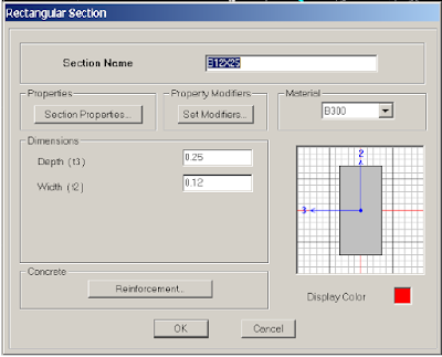
b
[Fig.3]
5- Define the slab section (see figure4).
 |
[Fig.4] |
6- Draw main Beams in both directions (user may draw beams as one line, or as segments; if beams is drawn as a one beam, user may use divide option to divide lines into segments). Now you must have as shown in figure 5 ( B70x25 at long direction, while B30x25 for short direction- you may check handout 5 figure 1).
 |
| [Fig.5] |
7- Draw secondary beams by following instructions in figure 6.
 |
| [Fig.6] |
8- Draw secondary beams by clicking at space between each 4 beams (see figure 7).
 |
| [Fig.7] |
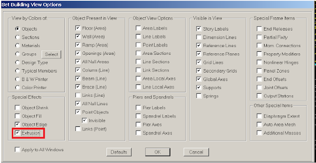
9- Now click at the 3D window then chose  and check Extrude option (see figure 8).
 |
| [Fig.8] |
10- User now must have this view (see figure 9).
 |
| [Fig.9] |
 |
[Fig.10] |
12- Draw S8 so you can have as shown at figure 11. After drawing the slab make sure fill object option is activated.
 |
| [Fig.11] |

14- To assign dead load to slab, first select the slab, here user will be introduced to a new selection method in Etabs (do as shown in figure 12).
 |
| [Fig.12] |
15- Assign the dead load (do as shown in figure 13).
 |
| [Fig.13] |
 |
[Fig.14] |
17- Define the load combinations (see figure 15).
 |
| [Fig.15] |
 |
| [Fig.16] |
19- To this moment, slab will act as a two way slabs; loads will be distributed to beams at both directions. To make slab action one way first select the slab (now do as shown in figure 17).
 |
| [Fig.17] |
20- Before having analysis done user must check the model (do as shown in figure 18).
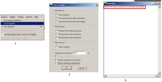 |
| [Fig.18] |
21- Now start Analysis (hit F5) or do as shown in figure 19.
 |
[Fig.19] |
22- User may check both deflection shape and moment results to make sure slab works as a one way slab (see figure 20).
 |
| [Fig.20] |
23- Now user may Design main beams, but first user has to remove secondary beams from view to improve the view options (see figure 21).
 |
| [Fig.21] |
Now user must have as shown in figure 22.
 |
| [Fig.22] |
24- To start design do as shown in figure 23.
 |
| [Fig.23] |
25- Now select beams to be designed (figure 24).
 |
| [Fig.24] |
26- See figure 25.
 |
[Fig.25] |
27- Now start the design of beams (see figure 26).
 |
| [Fig.26] |
28- The results shown is the longitudinal reinforcement area required for beams, values shown at top are for top steel, while bottom values are for bottom steel. Values shown are in m2 units, and this is why it look not clear, so user may change units to (KN cm) to improve the results view 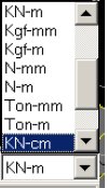
29- In addition to the last step user may improve the view by decreasing number of digits (see figure 27).
 |
| [Fig.27] |
30- User must have the same as shown at figure 28.
 |
[Fig.28] |
31- To display the design of shear reinforcement see figure 29.
 |
[Fig.29] |
Solving One Way System (Alternative No. 3):
The previous system will be solved using another alternative, do the following procedure to apply alternative # 3.
1- Unlock the model to get back to the stage before having analysis2- S8 (Slab 8 cm) will be modified to be membrane instead of being shell (see figure 30).
 |
| [Fig.30] |
3- B12x25 will be modified to be B12x17 (see figure 31).
 |
| [Fig.31] |
 |
| [Fig.32] |


No comments: