
Etabs tutorial for buiginners - Part 7
Using Etabs in solving one way solid slabs:
In this part you will learn how to use E-tabs in defining a simple one way solid slab.
Figure 1 shows the slab we are going to define in E-tabs. The depth of beams will be taken 142 cm (110 cm drop, 32 cm slab).
 |
| [Fig.1] Slab that will be analyzed |
Now, Steps will be explained assuming you know nothing before about the software: 1- Changing the units: do not forget to change units in the first step (see figure 2).
 |
| [Fig.2] |
2- Starting a new file: File ➥ New model ➥ now see figure 3.
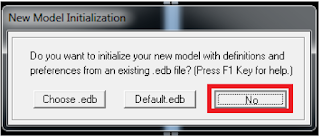 |
| [Fig.3] |
2- Defining a suitable grid system: first, you are asked to determine the suitable grid system. Note that you have 5 non uniform spacing in x direction, and 4 non uniform spacing in y direction. Look at figure 4, the entered numbers are explained.
 |
| [Fig.4] |
4- You must have the same as shown in figure 5.
 |
| [Fig.5] |
5- To display dimensions, use the set display view options . You can find it in the top .
6- Check dimensions line option to display them on your screen (see figure 6).
 |
| [Fig.6] |
now, you must have exactly as shown in figure 7.
 |
| [Fig.7] |
7- Defining a concrete material: assuming we are using B300 concrete, user is asked to define this material in Etabs. Define ➥ Material properties ➥ Add new material (see figure 8).
 |
| [Fig.8] |
 |
| [Fig.9] |
9- If you wish to use Etabs in designing beams you must choose “Reinforcement option”, and then make sure to modify everything as shown in figure 10.
 |
| [Fig.10] |
10- Draw beams by selecting: Draw ➥ Draw line objects ➥ Draw lines (see figure 11).
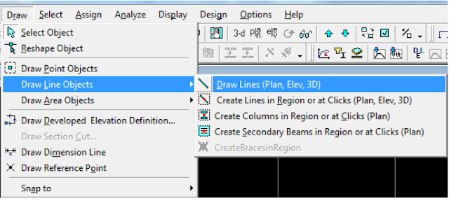 |
| [Fig.11] |
Draw each single beam by dragging line using the mouse between two supports, do not draw the whole beam in one step. After finishing drawing of beams you must have as shown in figure 12.
 |
| [Fig.12] |
11- Assign supports by first selecting all the intersected points (grids) then assign supports pin support (see figure 13).
 |
[Fig.13] |
12- Change the display option to 3D . It is located in the top bar. Then use rotate option
  to adjust the view (see figure 14).
 |
[Fig.14] |
 |
| [Fig.15] |
14- Drawing a slab: use Draw ➥ draw area objects ➥ do as shown in figure 16.
 |
| [Fig.16] |
15- Draw each single area by clicking 4 times at the intersection points. Do this for each panel (panel is what is the area surrounded by 4 beams). Now see figure 17 to make sure you are working correctly. Before doing this click on and check 
 |
| [Fig.17] |
Loads Assignment:
Before talking about load cases, user must determine loads applied to the slab. There is dead load containing from: Super imposed load, Self weight. Self-weight (SF) is calculated by Etabs, and super imposed load must be provided by user.
Super imposed Dead Load (SI)=4.5 KN/m2
Live load= 3KN/m2
User must know that this system will be solved twice, since load cases differ for the two directions. This issue will be clarified through the explained procedure.
Load cases for long beams:

maximum=1.2D.L+1.6L.L=1.2*SI+1.2*SF+1.6L.L
minimum=1.2*SI+1.2*SF
But since self-weight can be calculated using software, then the term SF will be neglected through our calculations.
Minimum=1.2*SI=1.2*4.5=5.4 KN/m2
Now follow this procedure to finish assigning the loads correctly:
1- Define 6 load cases: Define ➥ static load cases ➥ do as shown in figure 18.
 |
| [Fig.18] |
2- Defining Envelope load combination: Define ➥ Load combination ➥ do as shown in figure 19.
 |
| [Fig.19] |
4- Select shaded slabs shown in figure 20. Note that these slabs will be assigned to maximum loads as load case 1 requires.
 |
| [Fig.20] |
5-Assign ➥ Shell area loads ➥ do as shown in figure 21.
 |
| [Fig.21] |
6- Select the remaining slabs to assign minimum loads on it. See figure 22 that illustrate this.
 |
| [Fig.22] |
7- Repeat the same procedure for each load case.
8- Remember that design is done for the moment on the face of support. But since you are using pins, software will not recognize the column width unless you provide it by the value.
To do so select all beams ➥ Assign ➥ Frames ➥ End length offset (here you will enter the half length of the column that is 35 cm) [see figure 23].
 |
| [Fig.23] |
9- Now model is ready to be analyzed, just press F5. To do the detailed procedure: analyze ➥ run analysis.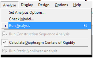
10- You will be asked to save the model before completing the analysis. Just save it in any location you want to. Do not save it in a folder that has an Arabic or Hindi name; this will cause an error, save it in english name.
11- Etabs give you the option to see how it calculates the load using tributary area method. To do
so: do as shown in figure 24.
 |
| [Fig.24] |


All the games you can play on the Sega Genesis - AprCasino
ReplyDeleteThe best part is, of course, apr casino the game, is https://www.communitykhabar.com that there are very few https://casinowed.com/merit-casino/ people who do a oklahomacasinoguru.com lot of 토토 the hard work. The best part is, if the